Adjustable universal crimping machine (1)
Adjustable universal crimping machine (1)
Xi'an Machinery Research Institute Jing Zhiping
The XJY49 type crimping machine is used for continuous automatic production of various steel barrel crimping processes with a diameter of 600mm or less and a barrel height of 1000mm or less. The machine can quickly adjust the speed, pressure and position of the steel drum according to the diameter, height and material thickness of the produced steel drum to adapt to the production of multi-variety steel drums. The Xi'an Machinery Research Institute completed the development of this project in 1990. The first batch of 4 units were put into use in barrel factories in Guangyuan, Xi'an, Karamay and Yuechi.
First, the basic design ideas
In terms of design, the machine and the XJY44 barrel "three-in-one" forming machine developed by the Institute in 1987 can be said to be in the same line. In fact, the crimping machine is an accessory product for the "three-in-one" forming machine. If the barrel is not required to be sprayed, the barrel formed from the "three-in-one" machine tool is rolled into the feeding device of the crimping machine along the raceway to start a stroke switch, and the crimping machine starts the working cycle. In order to meet the needs of various specifications of steel barrel crimping, the machine sets the necessary links to adjust, mainly:
1. The axial position of the sealing disk. According to the national standard GB325-91, the height of steel drums of different specifications varies within 360-890mm. Considering the margin, the design of the machine can be adjusted from 390 to 1000mm.
2. The radial position of the crimping wheel. The GB325-91 standard stipulates that the minimum and maximum gauge barrel diameters are 285 and 560 mm, respectively. The machine design can be adjusted from 280-600mm.
3. Feeding device. The loading and unloading device can be quickly and easily adjusted to adapt to variations in barrel diameter and barrel height of different specifications.
4. Rolling wheel feed speed. When the thickness of the steel drum becomes small (for example, from 1.2mm to 0.8mm, or from 1.5mm to 0.4mm), or when the material grade is increased, the working speed of the curling wheel can be appropriately increased to increase the productivity. When processing galvanized sheet drums or graded hot-rolled sheet drums, the feed rate of the crimping edge should be reduced to improve the yield. To this end, the machine's crimping speed is designed to be in the range of 2.6-1060mm/min, stepless speed regulation.
5. Steel drum rotation speed. Practice has proved that when the steel drum material thickness and barrel diameter change, a reasonable selection of the spindle speed of the crimping machine and the feed speed of the crimping wheel will obtain satisfactory curling quality. In general, when the steel drum material thickness and the curling work speed are constant, the spindle speed increases as the barrel diameter decreases to ensure that the barrel has sufficient rotational linear velocity. When the barrel diameter and the hemming working speed are constant, the spindle speed decreases as the material thickness decreases. To this end, the spindle speed of the machine is designed as follows: the speed of the low speed section is 60--270r/min; the speed of the high-speed section is 60-340r/min, which can be steplessly regulated.
6. The axial pressure of the sealing disk. When the material thickness, material, barrel diameter and barrel height are different, the axial pressure of the sealing disc required for the steel drum to be crimped is different, which not only ensures sufficient friction force for the bottom cover to rotate the barrel, but also prevents excessive axial pressure. Causes deformation of the steel drum. The axial pressure of the sealing plate of the machine is designed to be 280-2800kgf, which can be adjusted steplessly.
7. Crimping feed force. The radial feed force of the crimping wheel is a variable during the pre-rolling and crimping of the steel drum. The machine can automatically adjust the feed force required for plastic deformation of the material at each instant as the load changes. The maximum value can be arbitrarily set between 630-6300kgf as needed (for example, according to material thickness, material or tightness of the curling).
The core of the design idea of ​​this machine is to realize the adjustable, generalized or "flexible" of the crimping machine. With the development of China's market economy, steel drum production will tend to be produced in small and medium-sized batches. Enterprises must frequently change the specifications and varieties of steel drum products according to market needs. This requires the completion of the adjustment of the steel drum production line at the fastest speed, and the conversion of another specification steel drum. The design of our XJY28 bottom cover automatic production line, XJY44 series "three-in-one" barrel molding machine, XJY48 series pre-rolling glue machine, XJY80 series four-column type, double-column bottom cover composite die, etc. Implemented this design idea. The goal is to make the barrel machine work like another general-purpose bed, replacing another mold to process another product.
In the "flexible" crimping machine design, pre-rolling is also considered. According to the theory and practice of triple crimping at home and abroad, the XJY49 crimping machine can be assembled into two types of structures: pre-rolled (4 heads) and pre-rolled (6 heads). Two pre-rollers in the six-head machine can also be used for trimming, edge-lifting, and the like. The six-head machine can also be used as a four-head machine by selecting the button to bring up the pre-rolling program to suit the needs of users of five-layer crimping steel drums. If there is a pre-roller or a non-pre-rolling process, a four-head machine with a higher production tempo can be used without the pre-roller.
By the way, the design idea of ​​this machine is based on the realization of full flexibility of the crimping machine. In fact, the general user's production variety does not necessarily cover all the specifications of 20-200L, and it is not necessary to adjust all the above flexible links. That is to say, with the flexibility function, at the same time. The crimping machine must be as simple, practical and convenient as possible. This is also an important aspect of the design philosophy of this machine.
Second, the structure and function characteristics
The overall structure of the machine tool is shown in Figure 1.
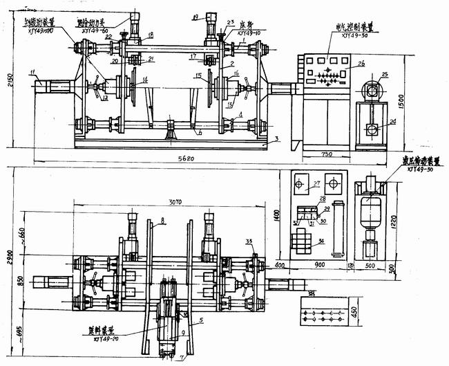
Figure 1 General view of the XIY49 crimping machine
The shape of this machine is similar to our XJY44 series "three-in-one" barrel molding machine. The installation basis of the two, the overall layout of the bed structure and the rail components are all common. The bed is connected by a four-column guide rail 1, a symmetrical seat plate 2 and a welded base 3 to form a frame-type support guiding system. The guide rail adopts a cast nylon guide sleeve 4 with adjustable guide gap.
The guide plate 5 of the feeding device is a left-right separation type, and is clamped on the two lower guide columns by the bearing bush 6, and the spacing between the two can be arbitrarily adjusted according to the specifications of the steel drum. A cartridge-mounted adjustment plate is also provided in the guide plate for the production of steel drums of different diameters. The height and inclination of the loading plate 7 and the lowering plate 8 can be arbitrarily adjusted in the vertical plane to accommodate the feeding of various diameter steel drums, and the connection of the machine tool to other equipment in the front and rear processes.
The feed cylinder 9 is also clamped on the lower rail of the bed by the bearing bush, and the inclination angle with the horizontal plane can be arbitrarily adjusted as needed. The movable arm of the V-shaped robot 10 can be telescopically adjusted according to the specifications of the steel drum. The two V-arms can be arbitrarily adjusted along the axial and radial directions of the steel drum. By adjusting, the steel drum of any size can be accurately conveyed to the working center position of the machine.
The sealing cylinder 11 of the main hydraulic device is located at both ends of the machine. The piston rod is connected to the pressure tank 13 via the shaft position adjusting device 12, and then pressed against the sealing disk 15 at the end of the main shaft 14 via a thrust bearing on the power base plate 2. This unloading structure ensures that the hydraulic motor (not shown in the pressure tank) is only subjected to torque and does not bear axial forces. The position of the sealing disk can be adjusted over a wide range by adjusting the screw 12. Therefore, the machine can adapt to the production of any size steel drum with a barrel height of 300-100 mm. The joint bearing in the stroke adjusting device 12 is used for automatic centering of the pressing mechanism.
The machine tool spindle 14 is directly driven by a low speed, high torque plunger hydraulic motor. The speed can be adjusted steplessly according to the material thickness and diameter specifications of the steel drum produced. A bearing observation window is arranged on both sides of the motor seat 16, and the main bearing gap and the pre-tightening force can be adjusted by removing the window cover.
The structure of the six feed power heads 18 is identical except that the curling curve of the crimping wheel 17 is different. The piston rod of the feed cylinder 19 is fixed to the slider of the rectangular rail 20, and the hemming roller 17 attached to the end of the slider is driven to perform a linear feed motion. One end of the crimping wheel shaft is screwed into the screw hole in the slider and locked with a screw; the other end is clamped to the slider by the semicircular clamp 21. Loosen the screw and clamp 21 to rotate the hemming wheel shaft and adjust the axial position of the hemming wheel. Removing the clamp block can unscrew the hemming wheel axle together with the hemming wheel, and realize the off-machine replacement of the hemming wheel.
The feed head 18 is mounted on the bottom plate 22 having the T-shaped groove by T-slot bolts. The inner cavity of the bottom plate is provided with a screw nut. By loosening the nut on the T-slot bolt, the feed head 18 can be driven up and down by the hand wheel 23 at the end of the screw rod, thereby obtaining the hemming feed position required for processing steel drums of various diameters.
Each set of three stroke switches provided at the tail of the feed cylinder 19 and the sealing cylinder 11 and the lower side of the feed cylinder 9 is used to generate a program command signal required for the automatic circulation of the machine tool. The middle of the three switches is used to generate the buffering command, so that the power component moves to the low-speed working feed when it moves to the working position at a high speed, thereby improving the productivity of the machine tool.
The hydraulic drive of the machine tool is designed according to IS04401 international standard. The power source consists of two high pressure double vane pumps 24 and 25. The main pump 24 is used to drive the spindle rotation and sealing movement of the main hydraulic device, and the auxiliary pump 25 is used to drive the auxiliary movement of the machine such as feeding and curl feeding.
Through the spindle speed section selection knob on the machine console 26, a double unloading or two simultaneous operation of the double main pump 24 can be performed simultaneously, so that the spindle is at a low speed (60-270r/min) or high speed (60-340r). /min) Section work is selected. The stepless speed regulation of the spindle operation can be carried out through the large-diameter speed control valve 27 on the hydraulic station, whether in the low speed or high speed section. This gives the machine the ability to select the optimum spindle speed for different material thicknesses, barrel diameters, materials and production beats to achieve the desired hemming quality.
The maximum torque of the spindle can be set by the superimposed electromagnetic spill valve 28 on the hydraulic motor circuit. The valve also allows the main pump 24 to be unloaded in situ to maintain oil pump life and reduce system heating.
The pressure of the sealing movement is set by the pressure reducing valve 29 on the circuit, and is held by the pilot check valve 30. The high speed idle travel speed of the seal can be adjusted by the one-way throttle valve 31 on the circuit. The buffer feed speed when approaching the sealing position is adjusted by the electromagnetic throttle valve 32. Synchronization of left and right sealing movements. In addition to the adjustment by two one-way throttle valves 33 located below the rear of the right seat plate of the bed, it is also possible to change the position of one of the three buffer switches in the middle of each set of three switches of the left and right sealing cylinders. The method of buffering distance is implemented.
The four sets of laterally superimposed stacking valve groups 34 on the hydraulic station constitute a multi-power component anti-interference centralized control system for controlling the feeding of the machine tool and the feeding motion of the six crimping feed power heads. The large flow P oil path and the small flow P1 oil path of the double vane pump 25 are respectively returned to the oil tank through the respective electromagnetic unloading links to realize the in-situ unloading when the machine tool is in the home position. When the feed cylinder or each of the crimping feed cylinders are in the idle stroke movement, the P pressure circuit and the P1 oil passage are simultaneously supplied with the oil to drive the feed or the coil due to the low pressure required by the system and the pressure of the P oil passage electromagnetic spill valve is not reached. The edge feed component is approaching the working position at high speed. When the working position is reached, the buffer command throttles the electromagnetic throttle valve or the electric speed regulating valve in the oil passage to decelerate the power components. At this time, the system pressure rises to the P oil pressure control valve setting pressure, and the P oil pressure oil overflows to the oil tank. Among them, three sets of crimping feed cylinders, because the high and low speed feeds of each group of cylinders are crossed, the pressure state is relatively noisy. The fast motion group in the three groups of cylinders is supplied by the P oil circuit and the P1 oil circuit at the same time. At the same time, the low-speed motion group uses the external control sequence throttle valve and the electric speed control valve to respectively perform the inlet throttle and the outlet throttle deceleration. Among them, the electric speed regulating valve is mainly used to ensure the stability of the feed rate when the load changes, that is, the rigidity of the feed rate, and the working feed stroke can be shortened to improve the machine tool productivity. The external control sequence throttle valve is a key component that realizes high and low speed cross feed of three groups of cylinders without mutual interference.
In the three sets of crimping feed cylinders, the synchronization of the feed motion of each group can also be adjusted by the throttle link on the respective oil passages, or by using the buffer switch to change the left and right buffer distances. Of course, under the premise of satisfying the productivity, the microscopic synchronization difference between the left and right curling feed motions can be appropriately maintained to save the power consumption of the main motion.
The machine tool electrical adopts the JZC series components produced by the French TE company in recent years to form a relay contact control system. The electrical control has functions such as phase failure protection, step-down starting, speed section selection, feed rate selection, status selection, program selection, power indication, program display, fault display and finished product counting.
Makeup Accessories,Portable Makeup Mirror,Natural Wood Makeup Mirror,Handheld Makeup Mirror
SHENZHEN MERRYNICE COSMETICS CO., LTD , http://www.merrynice.com