Application of hydraulic technology in steel drum machinery (1)
Application of hydraulic technology in steel drum machinery (1)
Xi'an Machinery Research Institute Jing Zhiping
Hydraulic drive technology has been used in steel drum manufacturing machinery almost at the outset. In the early 1960s, the barreling equipment produced by LEIFELD in the Federal Republic of Germany successfully used the hydraulic transmission to drive the radial feed of the main core, the rolling edger and the corrugator of the expansion machine. Machine tool movement and feed movement such as sealing feed of the crimping machine, as well as auxiliary movement of the machine such as steel drum feeding and component feeding. Companies such as CARANDO, Atlanta, BEIERI (ING), and GENER-AL MACHINE have also applied hydraulic transmissions to companies such as CARANDO, Atlanta, and GENER-AL MACHINE. It produces automatic seam welding machines, exhibition blanking production lines, barrel and bottom cover production lines. Although the development of steel drum machinery in China started late in this field, it has developed quite rapidly in the past ten years. This is because China has repeatedly examined some advanced steel barrel enterprises in Japan, the United States and Europe since the 1970s. It is an advanced paradigm and development direction for hydraulic transmission in steel drum machinery. Also due to the inherent advantages of hydraulic transmission technology, such as low-speed large-tonnage movement; mechanical automation can be simplified simply; the appropriate throttle technology can make the speed of moving parts very uniform and stable; Speed; the layout of the transmission has great flexibility; the volumetric weight is reduced by several times compared with the mechanical transmission; the transmission and clutching and the moving speed can be controlled with very little power; the transmission components are rarely worn due to self-lubrication; Standardization and generalization, and even international standards. Calmly reviewing and analyzing the decades of hydraulic machinery we have been engaged in, especially the development of barrel machinery in the past ten years, it is not difficult to see that the obvious fact is that hydraulic transmission can not be replaced by mechanical transmission in many applications. . It is often the most reasonable and sometimes even the only one that works.
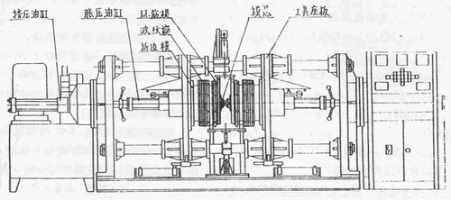
Figure 1 barrel joint forming machine
The development of the "three-in-one" joint forming machine for the barrel can be used as a typical example of hydraulic transmission in barrel making machinery. Figure 1 shows the overall structure of the machine. The basic design idea is how to complete the three steps of the flange, the corrugation and the ring rib on the machine. To this end, a "three-in-one" forming tool that combines the three molds of the extruded hemming mold, the expanded pressure corrugated mold and the ring-shaped mold is provided on the left and right sides of the machine tool. During work, the left and right forming tools are first advanced from the squeeze cylinders at both ends of the machine to the inside of the barrel, and the hem is folded when the hemming die is in the 'position. Thereafter, the expansion pressure cylinder mounted on the back of the tool seat plate pushes the expansion molding core to complete the expansion and compression forming of the corrugations and ring ribs. When exiting, the expansion cylinder first drags the core to reset the expansion mold, and then squeezes the cylinder and moves in the opposite direction to pull the entire forming tool out of the barrel.
It is not difficult to see that it is almost impossible to use the other mechanical transmissions to complete the movement of the above components on the "three-in-one" joint forming machine of the barrel. It is conceivable that if a motor is decelerated by a speed reducer, a screw nut is paid, or a gear rack is used, or a mechanical transmission device such as a cam mechanism is used instead of a squeeze cylinder and a pressure expansion cylinder in FIG. The transmission components to be set are: 4 motors, 4 reducers, 4 linear motion (screw nuts, etc.), 4 clutches (due to frequent starting of the motor), 4 brakes, and the support of these components. Connections and auxiliary devices. This not only doubles the volume and weight of the machine tool, but also makes the design of moving parts, especially the expansion and contraction parts, extremely difficult. At the same time, the processing range of the machine is 20~2001. Barrel body. When the barrel material, material thickness and size specifications are changed, the parameters such as pressure, speed and plastic deformation holding time of the extruded and expanded parts should also be adjusted accordingly. For mechanical transmissions, such adjustments are very complicated, and hydraulic transmissions are very simple and convenient.
The hydraulic drive not only doubles the size and weight of the machine, but more importantly makes the overall layout of the machine extremely simple and beautiful. It simplifies the cumbersome and heavy mechanical drive chain into two high-efficiency working cylinders, and the control of the pressure, speed and direction of the machine's motion is skillfully concentrated on a hydraulic station. In the past, the clutches and brakes that frequently fail due to wear and tear, in the hydraulic transmission, only need 40 watts of electromagnet to generate 40 Newton force to push a small reversing spool, so that tens of kilowatts or several The power components of the dry Newton meter are reliably clutched, braked and reversed. The noise of the "three-in-one" barrel forming machine is significantly lower than that of the mechanical three-machine barrel forming machine. Not only that, but the hydraulic drive also makes the automation of the "three-in-one" forming machine quite easy and convenient. The machine only needs to set a number of stroke sensing elements to send to the corresponding hydraulic reversing valve, and the power components are commanded to change their pressure, speed and direction according to a predetermined procedure, and the machine tool is automatically controlled by simple electrical program control.
The application practice of the "three-in-one" barrel machine also convincingly eliminates the "three fears" mentality of the hydraulic transmission: one is afraid of "normal leakage"; the second is afraid of "changing repair"; the third is afraid of lack of hydraulic technicians. The user of the first "three-in-one" forming machine in China - Shaanxi Huayin City Barrel Factory has been using the machine for six years since October 1989, including hydraulic equipment, the machine has never been overhauled. The hydraulic system is always leak-free and the work is stable and normal. The plant does not have a hydraulic professional and technical personnel, only the normal maintenance of operators and maintenance personnel. The application practice of 30 “three-in-one†hard suburbs in China shows that the hydraulic transmission of barrel machinery is feasible, reliable and advanced. The key here is the correct design of the hydraulic system.
Figure 2 is a hydraulic schematic diagram of the XJY44D "three-in-one" barrel machine. Since the machine is a pressure machine that plastically deforms the metal, it is designed to take a medium and high pressure (15-20 MPa) pressure section. At present, the comprehensive performance of the variable pump is still very unsatisfactory. In particular, the plunger pump has a high requirement for the cleanliness of the working medium, so the machine still uses the fixed pump system. Based on the idea of ​​relying on international standards and based on the selection of high-quality domestic components, the system adopts China's domestic FD series superposition valve and DC wet reversing valve in accordance with IS04401 international standard connection size, and China's Etos (AT05) in recent years. The company introduced the production of PFED series high pressure double vane pumps to form a centralized control system for multi-power components.

Figure 2 Hydraulic system diagram of the barrel joint forming machine
As shown in Fig. 2, the pressure oil generated by the pin-type double-vane pump 2 driven by the Y-series motor controls the operation of the six cylinders of the machine tool through the respective stacking valve groups. The pressure of the large flow pump (P oil passage) in the double pump is set by the external control sequence valve 9, and the pressure of the small flow pump (PI oil passage) is adjusted by the electromagnetic relief valve 10. The setting of the working pressure can be adjusted by means of the pressure gauge switch 15 and the pressure gauge 16. When the working load does not reach the set pressure of the external control sequence valve 9 (such as the forming tool feeding or exiting the barrel), the working cylinder is quickly operated by the dual pump at the same time. When the system reaches or exceeds the set pressure of the valve 9 (such as hemming and expansion), the P1 oil pressure oil opens the sequence valve 9 to automatically unload the large flow pump, and the motor power is all used to drive the small flow pump. This makes the Wangben metering pump system have the advantage of constant power control of the variable pump system. The change of speed in the extrusion and expansion pressure movement, in addition to the use of this constant power automatic variable control pound? The working cylinder is provided with a throttling mechanism to achieve the end point buffer, mainly through the photoelectric switch to control the solenoid valve 4 when approaching the working position Unload the large flow pump. When the machine tool is in the automatic working state, but the interrupted working program is judged to be abnormally required by the computer, the electromagnetic spill valve 10 is also turned on to completely unload the system. These unloading links greatly reduce power consumption and reduce system heating.
The four rows of superimposed valve groups on the left side of Figure 2 are used to control the reciprocating motion of the left and right squeeze (folded) cylinders and the left and right expansion pressure (corrugated, ring) cylinders. The two-column stacking valve group at the right end is used to control the lifting movement of the lifting, positioning (steel barrel clamping and loading and unloading) cylinders. The lifting speed can be adjusted by the throttle valve 13. The lifting positioning pressure can be adjusted by the pressure reducing valve 1, the pressure gauge switch 15 and the pressure gauge 16.
Silicone kitchen utensils and appliances, as a kind of household cooking class life appliance, its security is very important, in the choose and buy when we must to find regular vendors to buy, need to have food grade environmental protection product certification test report, or the FDA, LFGB certification test report of raw material, in the choose and buy when we should also pay attention to choose suitable for their own use of kitchen utensils and appliances, to distinguish between the use of a single kitchen utensils and appliances, before buying must use nose to smell a smell smell of products, strict silicone kitchen utensils and appliances in a heated encounter cold should not have any smell, in the white paper to wipe won't have any rub off phenomenon.
Silicone Insulating Gloves,Insulated Electrical Gloves,Electrical Safety Gloves,Electrical Lineman Gloves
Ningbo Sunmoon Silicone Product CO.,Ltd , http://www.sunsilicone.com