Design and Implementation of Ethernet Reader Based on W7100
In a solution for implementing a microcontroller device to connect to an Ethernet, it is common to use a microprocessor to connect to an Ethernet controller. At present, most Ethernet controllers are designed for PCs, such as DM9000 and CS8900A. The use of these chips is not only complicated but also costly and is not suitable as a solution for card reader networking.
The W7100 is WIZnet's new Ethernet microprocessor. The chip contains an 8-bit microprocessor core and hardware TCP/IP core. It integrates a 10/100 Mb/s Ethernet PHY layer, and the chip pins are directly connected to the network port socket without going through the physical layer chip. Its TCP/IP hard core provides a Socket socket interface, so only Socket programming is required to complete Ethernet communication, just as easy to access external memory, without involving the underlying control of Ethernet.
1. Basic features of the W7100
The W7100's CPU core is a high performance, rate optimized 8-bit embedded microprocessor. It uses on-chip memory for high speed operation and is compatible with industry standard 8051 microprocessor binary code. Its TCP/IP core is a full-featured, market-proven TCP/IP stack that integrates the MAC and PHY layers of Ethernet. The main features of the chip are as follows:
1), 64 kB program flash (Flash);
2), 64 kB SRAM;
3), 256 B data flash memory (can be used to store data that requires power-down protection, such as network configuration information);
4), built-in 10/100 Mb/s Ethernet physical layer;
5) The hardware TCP/IP protocol stack supports TCP, UDP, IPv4, ICMP, ARP, IGMP, and PPPoE;
6) Support 8 independent Socket communication, the internal 128B transmission buffer can quickly exchange data;
7) Support ADSL connection.
The chip can be simply understood as a combination of the TCP/IP hardware protocol stack, the Ethernet MAC layer, the Ethernet PHY layer, and the 8051 core. The above features of the W7100 not only meet the functional requirements of Ethernet card readers, but also make development less difficult.
2. Card reader function and interface chip selection
The main function of the Ethernet card reader is that the card reader accepts the user's card, and then sends the card number and other information to the server through the Ethernet, and the server queries and modifies the database table. To accomplish this goal, the reader needs to implement the following aspects.
1), the card function The card here is a common IC card, so it is necessary to implement the RF transmission and reception functions. The solution uses NXP's MFRC500 as the IC card reader chip. The chip is mainly used in 13.56 MHz contactless communication, and its internal transmitter can directly drive the near-operating distance antenna without adding active circuits.
2) The W7100 used by the Ethernet interface function scheme directly has this interface, and only needs to execute commands in the software. The chip leads to four differential signal lines connected to the RJ45 socket. The solution uses an integrated interface single-port RJ45 socket 13F-60LDNL with built-in transformer. The socket also has a data transfer indicator and a connection indicator.
3), USB interface function Considering how to set the card reader and remove the card swiping information in case of Ethernet failure or no connection to Ethernet, the scheme adds a USB interface as an emergency for this purpose. At the same time, because the W7100 has ISP (system programmable) function, the program can be downloaded through the serial port, so the added USB port serves as the interface for downloading the program. The scheme uses the CH341T of Nanjing Yuheng Electronics Co., Ltd. as the USB interface chip. The CH341T is a USB bus adapter chip that emulates an asynchronous serial port via the USB bus. The chip has a built-in transceiver buffer that supports simplex, half-duplex and full-duplex asynchronous serial communication. Under the Windows operating system of the computer, the driver of CH341T can emulate the standard serial port, so the host computer program can communicate with the card reader completely by serial port, and the program download can also be realized.
4), the external WatchDog found in a practical version of the chip in 2010, the WatchDog is unstable (the phenomenon that there will be a crash when the dog code and the dataflash code are written in the program), so the scheme chooses XCOR X5043. (2.7 V) as an external Watchdog. At the same time, the chip has a 4 KB SPI EEPROM as a data memory, which can be used to extend the internal dataflash to store data that cannot be lost.
5) Unique identification It is very difficult to uniquely identify each card reader on the network when the IP address is not fixed. The solution adds a set of 8-bit DIP switches to the reader, which is identified by assigning a different binary code to each reader. The card reader reads the value of the DIP switch at startup to set its own serial number. The 8 pins of the DIP switch can be connected to any of the W71004 general-purpose pins. It should be noted that all common pins of the W7100 must be externally pulled up as an output.
6) Setting the working status The card reader needs to run in the configuration state before normal use. At this time, the card reader receives the configuration parameters sent by the host computer configuration program to configure its IP address, MAC address, subnet mask, and so on. These data are stored in internal dataflash or external watchdog. The scheme adopts the dial switch to “1000 0000†as the configuration state, and the others are in the normal working state.
7), the indicator light and the buzzer brush once need a buzzer beep once and the indicator light flashes once to indicate that the card is successful. If the operation is not successful, the buzzer will sound a long alarm. If you enter the configuration state, the indicator light will change color. The scheme uses red and blue two-color LED lights as indicator lights, red for configuration status and blue for working status.
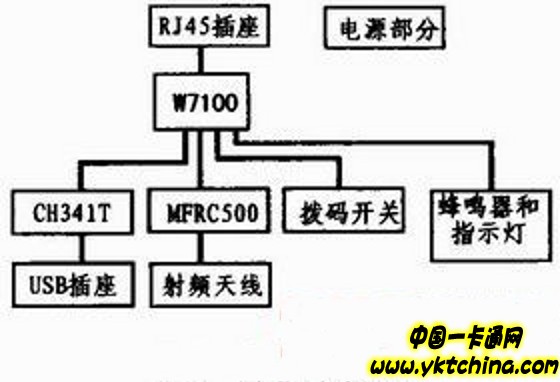
The structure of the card reader is shown in Figure 1.

3. Hardware circuit design
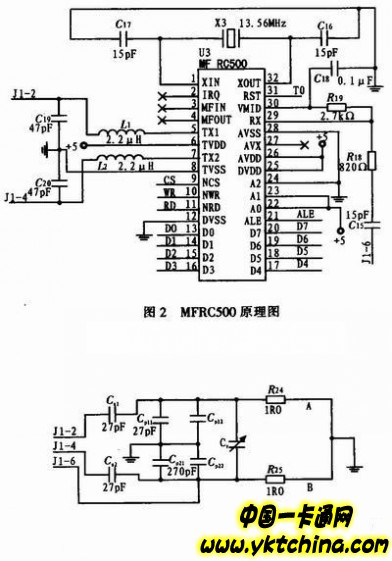
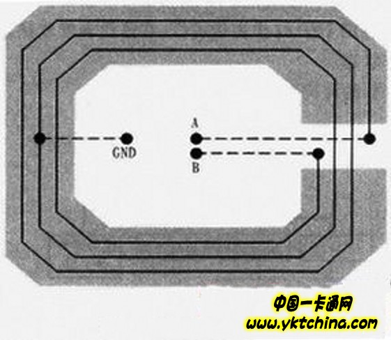
1), RF circuit As shown in Figure 2, MFRC500 needs to connect 8 data lines and 4 function pins, and connect to the antenna coil through 3 signal lines. The data line and the CS pin are connected to the general-purpose port of the W7100, and the ALE, WR, and RD pins are respectively connected to the corresponding function pins of the W7100. As shown in Figures 3 and 4, the antenna coil is wound by a ground wire (GND). In order to enhance the signal, it is usually necessary to add a shielding layer. The specific value of the adjustable capacitor is also adjusted according to the actual sensing distance.


2), RJ45 circuit Figure 5 is the reference schematic diagram of RJ45, four pairs of differential signal lines (TPTX+, TPTX-, TPRX+ and TPRX-) of RJ45 socket are respectively connected to the corresponding pins of W7100 (TXO-P, TXON, RXIP And RXIN).
Leather Backpacks are actually meant to be used daily as they are tough and not fragile like other material bags. The full grain leather bags are tanned with high-grade oils and preservatives which give a life of 30-40 years. So never worry about leather bags as they are always used by two generations.
Leather is a natural material, which is celebrated for its strength, durability and timeless style. ... Caring for a leather backpack is very simple and also very worth doing to keep the leather supple and long-lasting. When leather goods are cared for, they can last decades.
From leather backpacks to mini and practical options, we have something to suit you. Shop now with Jerryan.

Leather Backpacks
Faux Leather Backpack,Small Leather Backpack,Brown Leather Backpack,Leather Laptop Backpack
Guangzhou Jerryan Leather Co.,Ltd , https://www.jerryanbag.com