Bruner Control Strip for Offset Quality Control Method (1)
Use of Bruner Control Strips
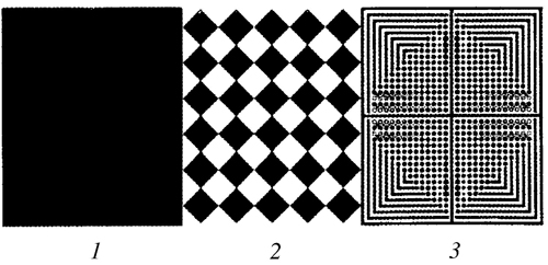
Bruner control strip is a quality inspection tool recommended by China's printing standards. It is used for measurement and calculation of field density, dot gain, dot distortion, and print contrast (K value) for proofing and printing. It can also be used for visual inspection. At present, most of the latest control bars with 7 control segments are used, but in practice The most commonly used print is the Brunel three-segment test strip (Figure 9-1). The following focuses on its role and use.
The role of a solid patch segment
(1) Measure the proofing, the density of the printed solid and the degree of ink inking.
(2) Measure and calculate the three major characteristics of three primary color inks, namely color shift, gray scale and efficiency.
The best field density value for controlling four-color inks is not only the core of color proofing for proofing and printing data, but also the core of data color management in the entire copying process. The picture shows that the solid density (ink layer thickness) has a great influence on the quality of proofs and prints. If the density is too large in the field, the dots will increase, the prints will be rough, and the density in the field will be too small. Therefore, the color saturation is insufficient. Therefore, the best spot must be achieved. Specifically, the optimal field density is 75% to 80%. The value of the maximum field density achieved when the outlets increase to a minimum or within a reasonable increase range. That is, the solid density at the maximum K value is the best solid density because the thickness and density of the ink layer have a close relationship as measured by a reflection densitometer. The absorption characteristics of the ink layer depend on the ink hue, the ink layer thickness, and the ink. The nature and density of the colorant.

(Figure 9-1 Bruner's Three-Stage Test Strip)
For the representative proofing, the field density range of the printed wet ink layer is shown in the table. In the actual proofing and printing process, not only must all process and technical measures be used to achieve the best field density value, but also the consistency of the density on the ground, such as proofing, must be consistent with the four-color density of five standard proofs. To achieve consistent left, middle, and right densities, the error is ±0.05D. In the printing, a product and a print are to be made, and the ink color from the start printing to the halfway through to the final printing is the same, which needs to be measured by controlling the conditions and the density meter to obtain.
Table 9-1 Proofing and Printing Thickness Range of Wet Ink on Different Substrates
 
C
M
Y
K
Coated paper
1.6
1.45
1.35
1.9
Asian paper
1.6
1.45
1.35
1.9
Writing paper
1.35
1.25
1.1
1.45
Newsprint
1
0.95
0.75
1.1
Note: The table value ±0.05 is the solid density range
Two 50% coarse network segments
The 50% thick section consists of 10 lines/cm dots with 50% dot area. Its main function is:
(1) Visually observe changes in dot gain and decrease directly.
(2) Calculate the increase of the 50% dot.
In actual production, operators often observe changes in the 50% coarse network segment, and use this to determine changes in network points, the general network points increase, 50% of the coarse network segment must take a serious angle, otherwise, the network spacing increase Large, the outlets decrease.
The above-mentioned dot gain value formula is of universal significance, and the calculation of the increase value of the 50% dot zone is based on the principle of the relative proportion of coarse and fine dots and is based on the principle that the total area of ​​coarse and fine dots is equal. The ratio of lines is 1:6, that is, the perimeter of a 50% fine mesh is 1/6 of the coarse mesh. The circumference of a row of 6 fine mesh points is equal to the circumference of a coarse mesh point. The sum of the 6 rows of fine dots is 6 times the coarse dots. Therefore, under the same conditions, the increase of fine meshes is very large. Therefore, based on the 50% thick mesh segment, taking the difference between the density of coarse and fine, the increase value of proofing and printing 50% dot area can be obtained. .
50% increase in dot area = (fine segment density - coarse segment density) × 100%
If the measured density of the 50% coarse mesh segment is 0.30, the density value of the 50% fine mesh area is 0.45, and the increase value of the 50% mesh area is substituted into the formula = (0.45-0.30) x 100 = 15%
This method is simple and accurate and is suitable for on-site management.
Yiwu Cnparacord Outdoor & Jewelry Factory , http://www.outdoor-paracord.com